Introduction
The 64 Channel Programable Anti-Aliasing Filter (AAF) is designed by me for the Ionospheric Science & Inertial Sensing (ISIS) Sounding Rocket Mission. The project is funded by the Alaska Space Grant Program (ASGP) & NASA Space Grant College & Fellowship Project and in collaboration with Tokai University & TPU University of Japan. The ISIS mission houses a total of 16 different instruments such as Magnetometers, Inertial Measurement Unit (IMU), Sun Measurement Unit (SMU), Flight Computer, Plasma Probe, Thermo Science Experiment, Telemetry (TM), Non-Pyro Door (NPD) etc. Four of the instruments have a serial optical fiber interface to the TM, but the reminder 12 instruments require anti-aliasing and thus the need for the AAF.
The sounding rocket will b an improved Orion and the mission is scheduled for launch from Poker Flat Research Range (PFRR) on March 2009.
Instrument Overview
The Anti-Aliasing Filter is a hybrid analog/digital system designed to meet the specific needs of the ISIS mission. Some key design features of the instrument are as follows:
- To keep instrument cost (< $2000) & real-estate to a minimum, the entire instrument is fitted onto four 4” x 4”, 2-layer PCBs with extremely high layout density.
- Each PCB houses 16 channels of 5-pole switched capacitor Butterworth filter with 1-pole Butterworth pre and post-filters providing a 65 dB per decade attenuation after the corner frequency.
- Instrumentation amps in the input stages allow accepting either single ended or differential signal inputs with a maximum difference voltage of 20 VDC.
- Remote programmability of corner frequencies from 1 Hz to 15 KHz is achieved using an MSP430 microcontroller, multiplexer, Analog Devices AD9510 clock distribution chips, RS485 & PECL to TTL level translators.
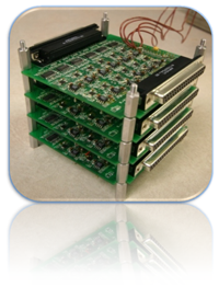
A picture of the completed hardware is depicted to the right. Each of the electronic boards are of 4" x 4" in size and 16 filtering channels. The clock generation and distribution circuitry is available on each of the four boards but the microcontroller that configures the clock frequencies is placed on the bottom most PCB. A multiplexer selects the appropriate clock generation module and required channel frequency is configured. |
|
|
|